
Design for manufacturing
Cellborne CNC Design Guidelines
Download PDF1.3 MBPurpose & scope
Design parts to these guidelines and they can be machined at Cellborne quickly, at the quoted price, without a design-for-manufacturing (DFM) back-and-forth. The rules apply to metal and plastic parts machined on Cellborne's 5-axis equipment.
- Recommended values are what to design to by default; they keep cost and lead time low.
- Minimum values are achievable but add cost, risk or inspection time; call them out on the drawing.
- Anything outside these limits is not refused outright. Send it for review and Cellborne will confirm feasibility before quoting.
- Dimensions are in inches with metric equivalents. When a drawing and a 3D model disagree, the drawing governs.
Cellborne capabilities
Cellborne machines small precision parts, up to 5 in (127 mm) in the longest dimension, on an automatic 5-axis cell with 100% 5-axis CMM inspection.
| Parameter | Metals | Plastics |
|---|---|---|
| Process | 5-axis CNC milling (Brother Speedio M200Xd1-5ax, 16,000 rpm) | Same |
| Maximum longest dimension | 5 in (127 mm) | 5 in (127 mm) |
| Minimum shortest dimension | 0.125 in (3.2 mm) | 0.5 in (12.7 mm) |
| Minimum feature size (suitable geometries) | 0.04 in (1.0 mm) | 0.04 in (1.0 mm) |
| Inspection | 100%, automatic 5-axis coordinate measurement | Same |
| Design data | 3D model required; drawing optional; MBD and GD&T supported | Same |
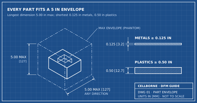
The longest dimension of the finished part must fit within 5 in; its thinnest section must meet the material minimum.
- Why plastics need 0.5 in minimum: plastics deflect and move under clamping and cutting heat, so very thin or small plastic parts cannot be held and cut accurately.
Materials
Choose aluminum 6061-T6 unless the application needs something else; it machines fastest and is the lowest-cost option. All materials are sourced traceable from reputable suppliers.
| Group | Supported grades | Design notes |
|---|---|---|
| Aluminum | 6061-T6/T6511, 7075-T6, MIC-6 | 6061 is the default. 7075 for high strength-to-weight. MIC-6 cast plate for flat, stable plates and fixtures. |
| Carbon & alloy steel | 1018, 1215, A36, 4130, 4140, 4140PH, 4340 | 1215 is free-machining (lowest cost steel). 4130/4140/4340 for strength; specify heat-treat condition. Steels rust; plan a coating or oil. |
| Stainless steel | 303, 304/304L, 316/316L, 17-4PH, 410, 416 | 303 and 416 are free-machining. 316 for corrosion resistance. 17-4PH for strength + corrosion. Expect higher cost and longer lead time than aluminum. |
| Engineering plastics | Acetal homopolymer (Delrin 150), Acetal, PTFE (Teflon), PEEK, Acrylic, PVC, ULTEM, UHMW-PE, Polycarbonate (PC), HDPE, ABS | Acetal is the default: stiff, stable, machines cleanly. PTFE, UHMW and HDPE are soft and move with temperature; loosen tolerances. PEEK and ULTEM for heat and chemicals. |
- Specify the exact grade and temper on the drawing (for example "Al 6061-T6"), not just "aluminum".
- Materials not listed can be reviewed on request.
Tolerances & surface finish
Metal parts hold ±0.005 in (±0.13 mm) on size and location and ±0.002 in (±0.05 mm) on hole size; flat metal faces reach 63 µin Ra (1.6 µm). Tighten only the features that need it.
| Feature | Metals | Plastics |
|---|---|---|
| Size / location (standard) | ±0.005 in (±0.13 mm) | ±0.010 in (±0.25 mm) |
| Hole size | ±0.002 in (±0.05 mm) | ±0.010 in (±0.25 mm) |
| Flat-surface finish, as machined | 63 µin Ra (1.6 µm) | Not applicable. |
| Contoured / side-wall finish, as machined | 63–125 µin Ra (1.6–3.2 µm), typical | Not applicable. |
Contoured and side-wall finishes depend on part geometry and tooling; the range shown is typical.
- Untoleranced dimensions are machined to the standard size/location tolerance above. State a title-block default on drawings so there is no ambiguity.
- Tolerance only what matters. Each tight tolerance adds machining passes and inspection time. Mating fits, bearing bores and datum faces deserve them; cosmetic outer faces do not.
- GD&T: define datums on faces that are machined in the same setup as the critical features, and on surfaces large enough for the CMM to probe (≥ 0.125 in / 3 mm wide).
- Plastics expand with temperature and relax after machining; PTFE, UHMW and HDPE may need looser limits than the table shows.
- Finishes: parts ship as machined. Note any cosmetic face on the drawing so tool marks and fixturing are kept off it.
Feature & face accessibility
Every machined feature needs a straight line of sight for a rotating tool from one of the five faces the 5-axis machine can reach in a single setup. The sixth face is held by the fixture.
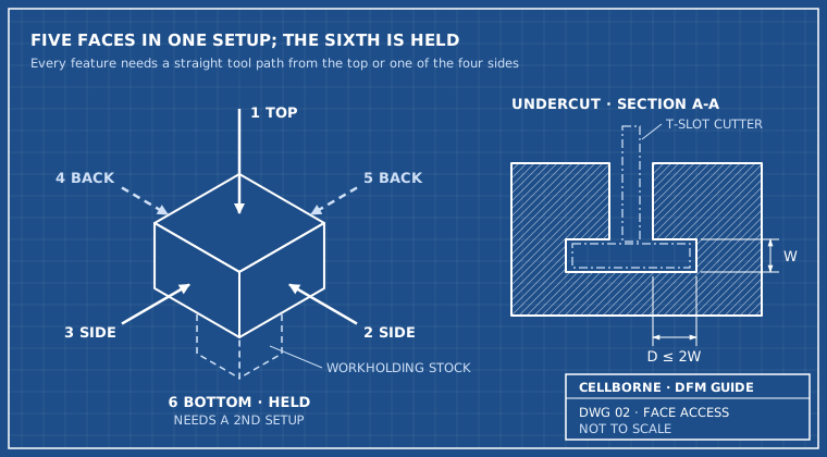
Faces 1–5 are machined in one setup; the bottom face needs a second. Undercuts are cut with a standard T-slot or dovetail cutter.
- Five faces, one setup. Top and all four sides, plus angled faces and holes, can be machined without re-clamping. This keeps features on those faces accurately located to each other.
- The held face. The bottom of the stock is clamped. Parts that need features on all six faces require a second setup, which adds cost and loosens face-to-face location. Put critical relationships on the five accessible faces.
On the 5-axis machine the part tilts and rotates under a cutting tool that only moves straight down, so five faces are machined in one clamping. The clamped sixth face needs the part flipped into a second setup.
- Tool reach. Keep the line from the spindle to the feature clear of the part itself. Deep features next to tall walls force longer, slower tools.
To cut a boss's round wall, the end mill has to run parallel to the boss. Keep that straight path clear: a shelf, lip or overhang above the boss blocks it, and the boss can't be machined as drawn.
- Undercuts. Avoid them. Where needed, use standard T-slot or dovetail profiles, keep undercut depth ≤ 2× the slot width, and leave open space opposite the undercut of at least 4× its depth so the cutter head can enter.
- Enclosed or internal cavities that no straight tool can reach cannot be machined; split the part into machinable pieces and assemble them, or consider 3D printing.
- Angled features. Holes and faces at compound angles are fine on 5-axis. Give them a flat entry face perpendicular to the hole axis so drills don't walk.
- Workholding stock. Allow material below the part for clamping, which is removed afterward.
Minimum feature sizes
No feature can be smaller than 0.04 in (1.0 mm), Cellborne's minimum feature size; design to the recommended column whenever the part allows.
| Feature | Recommended | Minimum / limit | Why it matters |
|---|---|---|---|
| Wall thickness, metals | ≥ 0.06 in (1.5 mm) | 0.04 in (1.0 mm) | Thin walls chatter, deflect and lose tolerance. |
| Wall thickness, plastics | ≥ 0.10 in (2.5 mm) | 0.06 in (1.5 mm) | Plastics flex and warp from cutting heat. |
| Unsupported wall height | ≤ 4× wall thickness | 8× wall thickness | Tall thin walls vibrate; add ribs or thicken the base. |
| Internal (vertical) corner radius | ≥ 1/3 of pocket depth, and slightly larger than a standard tool radius (e.g. 0.130 in, not 0.125 in) | 0.02 in (0.5 mm) | Round tools cannot cut square inside corners. |
| Pocket floor-to-wall fillet | 0 (sharp) or a standard ball/bull radius | — | Sharp floor corners are cheapest. |
| Pocket / cavity depth | ≤ 3× pocket width | 6× pocket width | Deep pockets need long, slow tools. |
| Hole diameter | Standard drill size, ≥ 0.125 in (3 mm) | 0.04 in (1.0 mm) | Standard drills are fast and accurate. |
| Hole depth | ≤ 4× diameter | 10× diameter | Deep holes risk drill breakage and wander. |
| Thread size (tapped) | ≥ #4-40 / M3 | #2-56 / M2 | Small taps break easily. |
| Thread depth | 1.5× nominal diameter | 3× nominal diameter | Engagement beyond 1.5× adds little strength. |
| Bosses, pins, ribs | Diameter or width ≥ 0.08 in (2 mm), height ≤ 4× width | 0.04 in (1.0 mm) | Slender features bend under cutting load. |
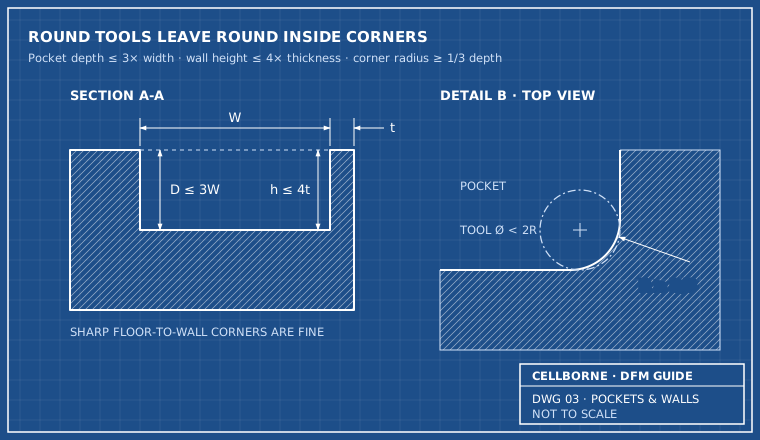
Deep narrow pockets and tall thin walls force long, slow tools; a generous inside radius lets a larger tool cut the corner.
An end mill is round, so it always leaves a radius in an inside corner. Design that radius in, slightly larger than the tool's, and the corner comes out clean.
A long, thin feature acts like a diving board: the cutter pushes the tip away, it chatters, and it springs back with material left on. Keep pins and bosses within 4× their width, or design support material near the tip.
Holes and threads
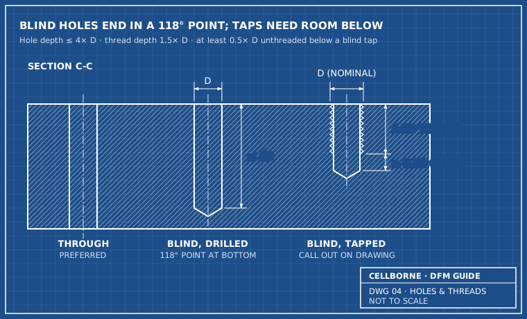
Through-holes are cheapest and most accurate; a blind tapped hole needs drilled depth past the last full thread.
- Blind holes have a 118° drill-point cone at the bottom; model them that way, or call out a flat bottom (milled, slower).
- Leave unthreaded depth below a blind tapped hole of at least 0.5× the nominal diameter so the tap does not bottom out.
- Specify threads by callout (for example "1/4-20 UNC-2B × 0.38 deep"), not by modeled helix. Modeled threads are ignored.
- Through-holes are cheaper and more accurate than blind holes; use them where function allows.
- Avoid holes that break out on a curved or angled face; add a spot face or flat.
Edges and corners
- External edges are deburred; call out a chamfer (e.g. 0.010–0.020 in × 45°) rather than an external fillet, which takes a special tool.
- Keep all internal radii in a part the same size where possible so one tool cuts them all.
One chamfer mill cuts any chamfer size by changing its depth. A corner-rounding mill cuts only the radius it was ground to, so each fillet size needs its own tool.
Text, cost drivers & pre-RFQ checklist
Text and markings
- Laser marking is faster and cheaper than engraving; choose it where you can.
- Engrave (recessed) rather than emboss (raised); engraving needs only the text cut, embossing needs everything around it removed.
- Use a bold sans-serif font, stroke width ≥ 0.04 in (1.0 mm), character height ≥ 0.12 in (3 mm), depth 0.010–0.020 in (0.25–0.5 mm).
- Place text on a flat face reachable from one of the five accessible faces.
What drives cost (highest impact first)
- Number of setups: features on the held sixth face, or that no single orientation can reach.
- Tall, slender parts: they flex like a diving board under cutting load and may need extra setups or support material.
- Tight tolerances and tight finishes beyond the standard values.
- Small tools: tiny corner radii, deep narrow pockets, small threads.
- Material: stainless, alloy steel and PEEK/ULTEM cost more to buy and to cut than 6061 or acetal.
- Thin walls and slender features that force light, slow cuts.
- External fillets: each radius needs its own special tool, so choose chamfers where you can.
Before you submit an RFQ
- Part fits within 5 in (127 mm) longest dimension, and meets the minimum shortest dimension (0.125 in metals / 0.5 in plastics).
- Material grade and temper are specified.
- No feature, wall or hole is smaller than 0.04 in (1.0 mm).
- Internal corner radii are ≥ 1/3 of pocket depth and not smaller than 0.02 in.
- Every feature is reachable in a straight line from the top or one of the four sides.
- Tight tolerances are applied only to functional features; a default tolerance is in the title block.
- Threads are called out on the drawing, not modeled.
- Cosmetic faces are marked.
- 3D model (STEP preferred) is attached; a drawing is included when tolerances, threads or finishes are critical.